
Toughness
Toughness is part of the material's core identity, in the same way as its elastic modulus or its yield strength. It is therefore a factor that influences design, and as such it is often a criterion used to select materials for a given application.
It is defined by
\(K_{IC} =\alpha \cdot \sigma_\infty \cdot \sqrt{\pi \cdot a_c}\)
where \(a_c\) corresponds to the critical crack size for the applied stress \(\sigma_\infty\). The crack size does not in itself provide any information about whether or not it is dangerous. It is necessary to know the stress applied \(\sigma_\infty\), calculate the stress intensity factor \(K_I\) and compare this with the toughness \(K_{IC}\).
The following table provides critical crack size values for a few materials as a function of the stress applied.
\(K_{IC}\)\({\rm (MPa.m^{1/2})}\) | \(UTS\)\({\rm (MPa)}\) | \(a_c\)\({\rm (mm)}\) | |||
|---|---|---|---|---|---|
\(\frac{\sigma_\infty}{YS ({0.2}{\%}proof) }=1\) | \(\frac{\sigma_\infty}{YS ({0.2}{\%}proof) }=0,5\) | \(\frac{\sigma_\infty}{YS ({0.2}{\%}proof) }=0,33\) | |||
2014 | 40 | 500 | 2 | 8,1 | 18,3 |
\(\ce{TA6V}\) | 85 | 1020 | 2,2 | 8,8 | 19,5 |
\(\ce{40CrMoV20}\) | 42 | 1850 | 0,16 | 0,65 | 1,4 |
\(\ce{35NiCrMo16}\) | 95 | 1850 | 0,84 | 3,3 | 7,5 |
ceramic | 5 | 800 | 0,0012 | 0,05 | 0,11 |
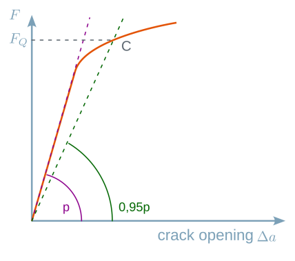
Toughness is generally determined experimentally via a tensile test performed at low strain rate on a specific test piece (test piece \(CT\): compact tension) including a mechanical notch and previously pre-cracked in fatigue (pre-crack size \(a_0\)). The low strain rate tensile load leads to a fracture of the test piece. Graphically, the intersection between a line with a slope equivalent to \({95}{\%}\) and the elastic line relating the force to the crack opening corresponds to a force of \(F_Q\). This force is a function of a parameter \(K_Q\) expressed in unit of toughness (\({\rm MPa.m^{1/2}}\)). If specific geometric conditions are met, then \(K_Q = K_{IC}\) (see following figure).


\(K_Q = \frac{F_Q}{t\sqrt{w}}. f \left( \frac{a}{w}\right)\)
For us to consider that \(K_Q = K_{IC}\), the size of the plastic zone has to be small in comparison to the ligament \((w-a)\), which requires that
\(a \geq 2,5 . \left( \frac{K_Q}{R_{0,\,2}} \right) ^2\)\(t \geq 2,5 . \left( \frac{K_Q}{R_{0,\,2}} \right)^2\)
Although simple to describe, in reality the test is complex and costly:
suitable crack propagation is only ensured if all faces of the test piece are perfectly ground,
satisfactory initiation is only ensured if the radius of curvature of the notch root is accurate,
pre-cracking must end with low stresses so as to end up with a small dimension plastic zone at the crack tip prior to the monotone tensile phase,
all together, eighteen conditions have to be successively checked in order to conclude that the parameter \(K_Q\) calculated does indeed correspond to the toughness of the material.
The approach developed in fracture mechanics differs fundamentally from that adopted in standard strength of materials approach where the stress applied is compared only to the yield strength or the ultimate tensile strength of the material. In fracture mechanics, we have to consider not only the stress applied, but also the occurrence and size of cracks present in the material as well as the material toughness (following figure).

The main questions arising from the study of the mechanical behaviour of cracked parts are:
what is the residual strength depending on the length of the cracks?
what crack size can be tolerated under working loads (critical size)?
how long does it take for a crack to propagate from a given initial size to the critical size?
what size of pre-existing defect is acceptable when a part enters service?
what is the frequency at which the part must be inspected?
Therefore, the study of fracture behaviour of materials requires a multi-scale approach that broadly covers the domains generally explored by materials science and applied mechanics (following figure).
